Tips
What are the three methods of DC/DC converter? :
step-down (buck), isolation (flyback), and isolation (forward)
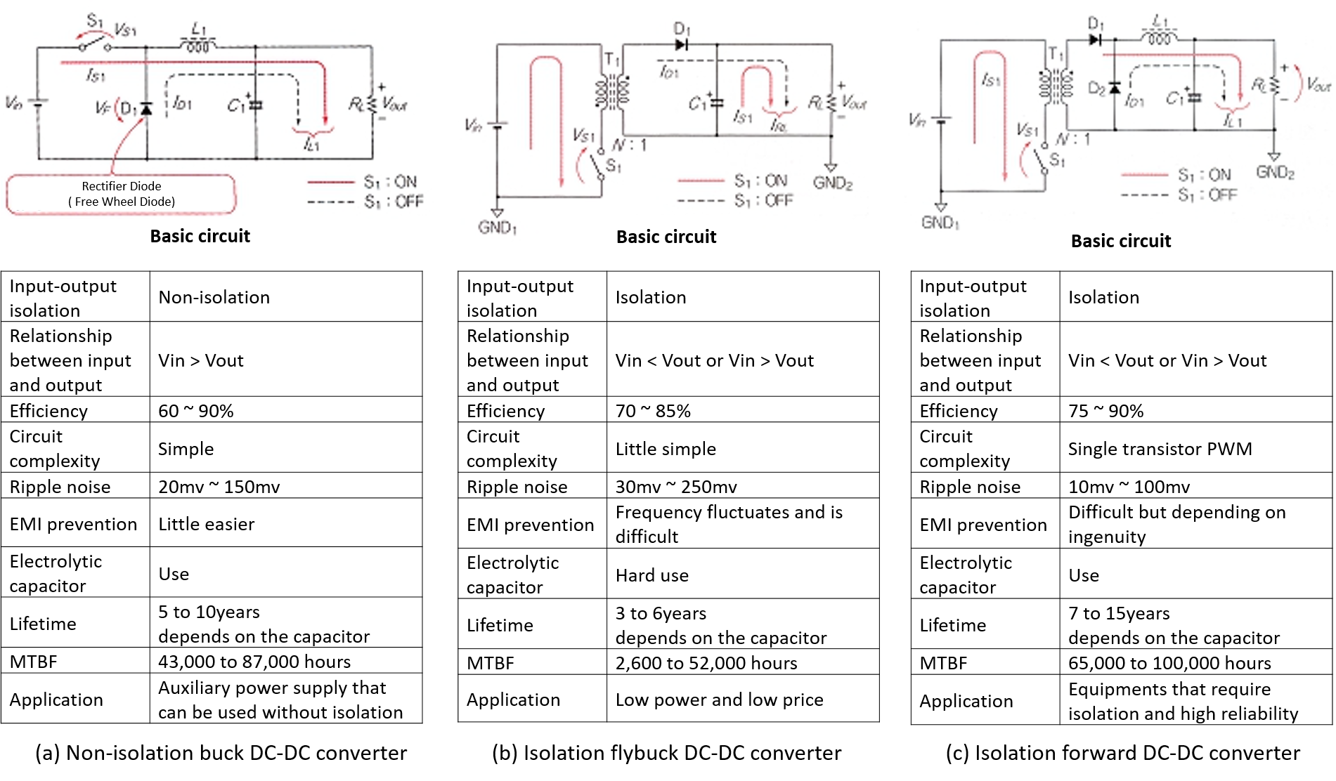
Fig.1 Types of DC-DC Converter
There are many circuit methods for DC-DC converters, but they can be broadly divided into non-isolation type (1) and isolation type (2).
The most frequently used non-isolated converter is step-down DC-DC converter called buck method.
Fig. 1 (a) is the basic circuit of step-down converter.
Switch S1 is a power transistor or a power MOSFET, and achievs the constant voltage by changing the ON / OFF ratio of these switching elements.
When switch S1 is ON, current flows through inductor L1 to the load RL.
When the switch S1 is OFF, the energy stored in the inductor L1 is transferred to the load through the rectification diode D1, then the constant voltage control is realized.
Recently, products with a switching frequency of 3MHz class have been put on the market, and the efficiency is as high as 90% to 94%.
The POL converters generally refer to this buck-type regulator.
This method can be expected to be small and low price.
The basic circuit of the isolated flyback converter is shown in Fig. 1 (b).
The flyback converter is a single transistor ON / OFF control converter, and the primary and secondary windings of the transformer are connected in reverse polarity. During the switching element S1 is ON, the primary side of the transformer stores energy, and during the OFF period, the energy released from the secondary winding is half-wave rectified by the rectifier diode D1 and the decoupling capacitor C1.
The feature of this method is that the rectification on the secondary side is a capacitor input type and does not use a filter inductor.
Therefore, the number of parts used is small and the price can be reduced, but in the case of a low voltage and high current converter, the ripple current of the capacitor increases, which is not suitable for low voltage and high current.
In addition, while there is an advantage that there is no choke coil needed, there is also a disadvantage that the isolation transformer becomes large.
The feature of this method is to control the amount of energy stored in the transformer.
Fig. 1(c) is a forward converter.
This method is a single transistor ON / ON control method.
This is a method of transmitting power to the secondary side via a transformer when the primary side switching element S1 is ON.
When switch S1 is turned on, energy is transferred to the secondary side at the same time ratio, and rectified and stabilized direct current can be obtained by the rectifying diodes D1 and D2, inductor L1, and decoupling capacitor C1.
Due to the choke input, the ripple current to the decoupling capacitor C1 is small and suitable for low voltage and high current.
The features of each circuit method are shown in the figures and tables.
It is important to choose correct type of converter through understanding each characteristics such as non-isolation, isolation, output voltage / current, lifetime, and size.
- Written by Shotaro Suzuki